Introduction to Ceramic Capacitors
Learn more about finding the right capacitors for your specific application.
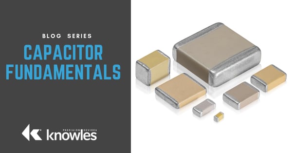
Welcome to the Capacitor Fundamentals Series, where we teach you about the ins and outs of capacitors – their properties, product classifications, test standards, and use cases – in order to help you make informed decisions about multilayer ceramic capacitors (MLCCs), single layer ceramic capacitors (SLCs), and trimmers. At Knowles Precision Devices, our expertise in capacitor technology has helped developers working on some of the world’s most demanding applications, such as medical devices, military and aerospace, telecommunications, automotive, and many more.

Table of Contents
Choose a topic of interest ranging from capacitor basics to dielectric types to user guidelines.
Part 1 – What is a Capacitor?
This first blog post in the fundamental series discusses the key principles of capacitance and how a basic capacitor works. This blog covers topics including the key principles of capacitance, what a capacitor is, and how a basic capacitor works.
Part 2 – How are Capacitors Used?
Capacitor technology covers a wide range of product types, based on a multitude of dielectric materials and physical configurations. This blog showcases the most common use cases for capacitors and how they can apply to your specific projects.
Part 3 – Factors Affecting Capacitance
For any given voltage, the capacitance value of the single plate device can be calculated from the geometry and dielectric constant of the device. Learn more about factors that impact capacitance in this post.
Part 4 –Dielectric Polarization
When an electric field is applied to a capacitor, the dielectric material (or electric insulator) become polarized, such that the negative charges in the material orient themselves toward the positive electrode and the positive charges shift toward the negative electrode.
Part 5 –Dielectric Properties
The perfect insulator has no movement of free electrons and possess infinite electrical resistivity. However, real-world insulators contain impurities and defects in their atomic lattice structure that give rise to charge carriers, resulting in some amount of leakage current under an applied electric field.
Part 6 –Ferroelectric Ceramics
Paraelectric dielectrics have a very linear relationship between polarization and an applied electric field, such that an applied field causes displacement in the ions (i.e., ionic polarization) and then the removal of the field causes the ions to return to their original positions.
Part 7 – Linear Dielectrics
Non-ferroelectric dielectrics show a linear relationship of polarization to voltage and are formulated to have a linear temperature coefficient. These materials consist primarily of TiO2 and therefore exhibit lower dielectric constant (less than 150). More importantly, they have lower dielectric loss and no aging of capacitance with time.
Part 8 – Dielectric Classification
Different dielectric materials all have their own characteristics and practical uses. Generally speaking, there is a trade-off such that dielectrics with a higher dielectric constant K have greater losses and less stability in terms of temperature, voltage, and time.
Part 9 – Test Parameters and Electrical Properties
Electrical behavior of ceramic chip capacitors is strongly dependent on test conditions, most notably temperature, voltage and frequency. This dependence on test parameters is more evident with Class II ferroelectric dielectrics, and negligible or more easily predictable with Class I formulations.
Part 10 – Industry Test Standards
Chip capacitor test parameters, performance specifications, and quality conformance requirements are outlined in the EIA 198 and MIL-C-55681 specifications. We’ve put together a summary of electrical specifications for popular Class I and Class II dielectrics.
Part 11 – High Reliability Testing
Product durability and accelerated life cycle testing are all methods of determining the reliability of a product before release. By subjecting the capacitor to elevated conditions far beyond its normal operational ranges, we seek to discover any defects or points of failure to better inform customers about the limitations of the unit.
Part 12 – Visual Standards for Chip Capacitors
Multilayer ceramic capacitors (MLCCs) must possess fine workmanship and physical integrity, so visual inspection of the product is performed at 20X magnification to check for defects in the capacitor body and end metallization.
Part 13 – Soldering for Chip Capacitors
Traditionally, leaded capacitors were used in high volume printed circuit boards (PCBs), such that the components were assembled or “stuffed” into plated through holes on P.C. boards. Nowadays multilayer ceramic capacitors (MLCCs) are often sold as chip (or leadless) components that can be surface mounted to high-density boards using high speed automation. However, variables affecting attachment of chips to substrates are of increasing importance. The inherent mismatch of thermal and physical properties of the components to the substrates and solders is intensified by the use of chip components directly bonded to the substrate material. In this article, we discuss different chip capacitor attachment methods, thermal properties, and performance specifications to consider.
Part 14 – Useful Formulas and Calculations for Capacitors
When it comes to practical applications, a real-world capacitor is not perfect, such that the voltage and current across it will not be perfectly 90 degrees out of phase. The angle by which the current is out of phase from ideal can be determined, and the tangent of this angle is defined as loss tangent or dissipation factor (DF).


